Radial ports, a deep bore and seven metal inserts compete for mold space and create linked manufacturing challenges. Our review connects core release, cooling and assembly into one proposed process.
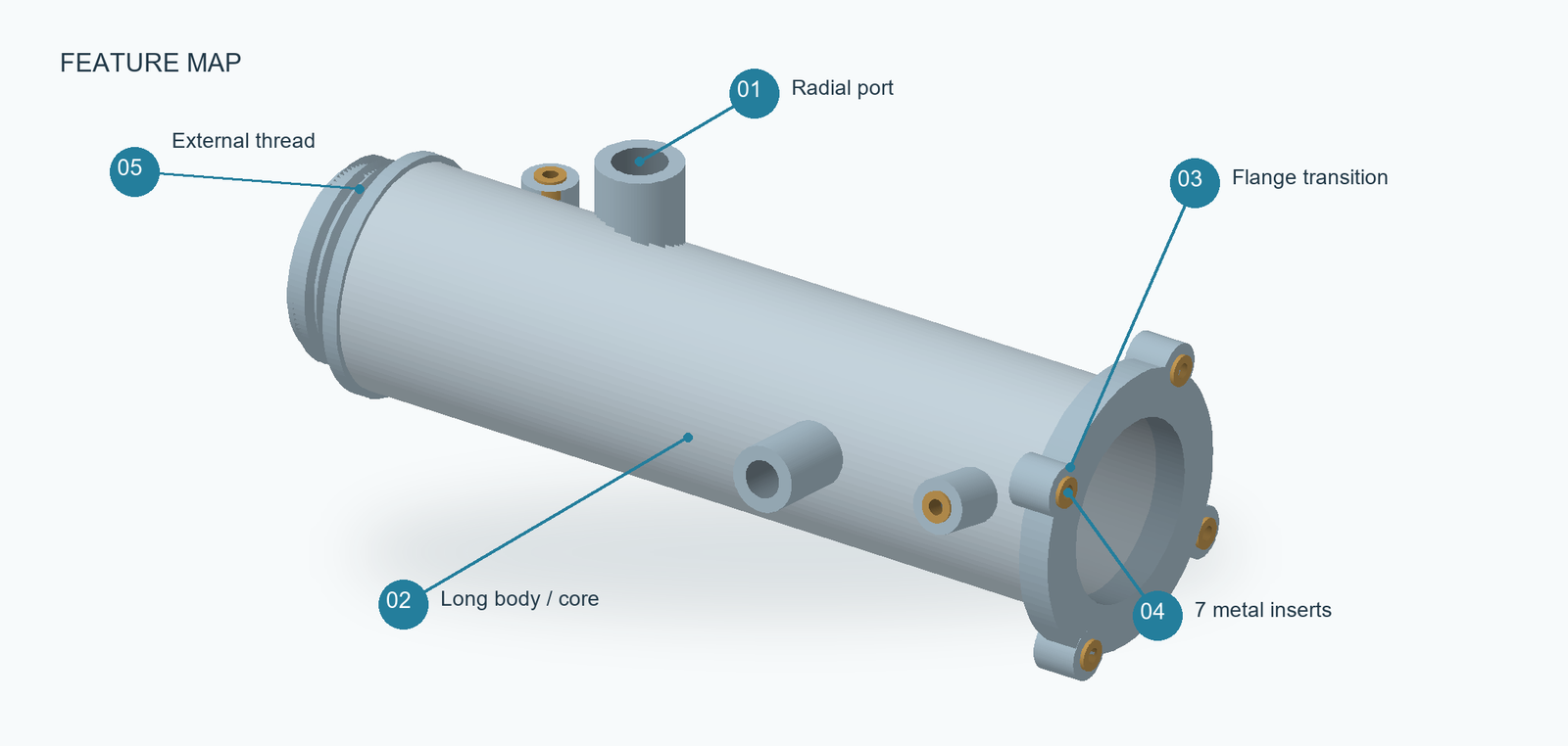
Feature map / numbers correspond to the analysis below.Redrawn engineering illustration; not the customer's original CAD.
Our engineering approach
Three decisions. One coordinated process.
Resolve how the geometry, mold movements and assembly sequence interact before detailing the tooling.
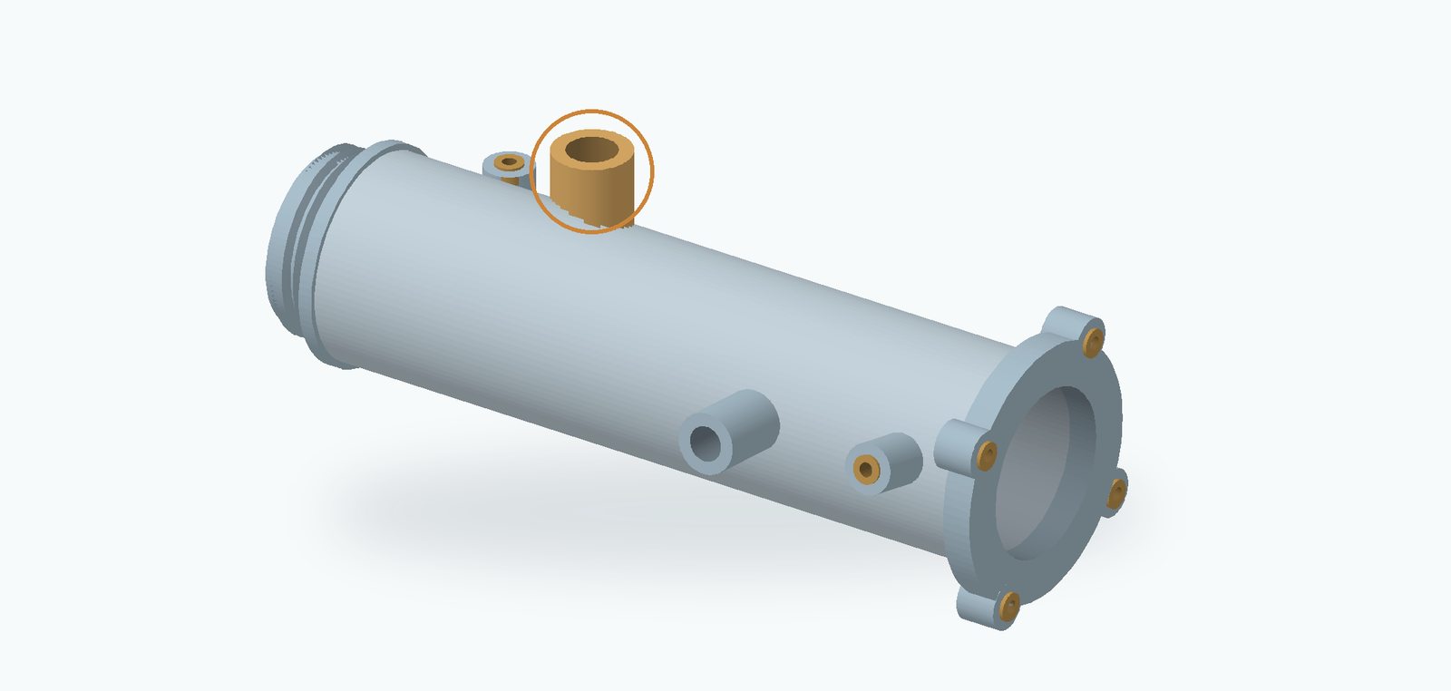
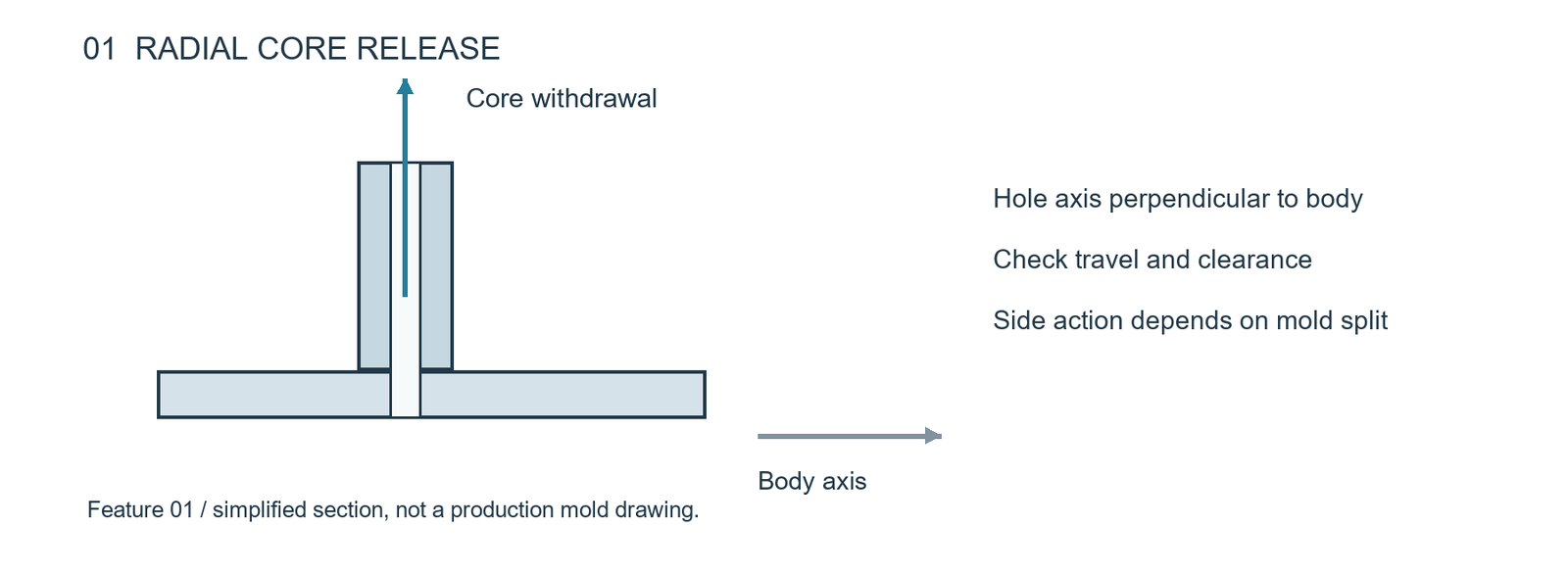
Feature 01 / from the complete housing to the local core release.
01 Core release
Release each port along its own hole axis
The ports point in different radial directions. Axial withdrawal of the long core cannot release every port core, while crowding all movements into one mechanism complicates clearance and maintenance.
Our recommendation
Use the mold-opening motion where the hole axis permits it, and dedicated slides for the remaining directions. Release radial constraints before axial demolding. Design the port-core / long-core shutoffs separately to control flash.
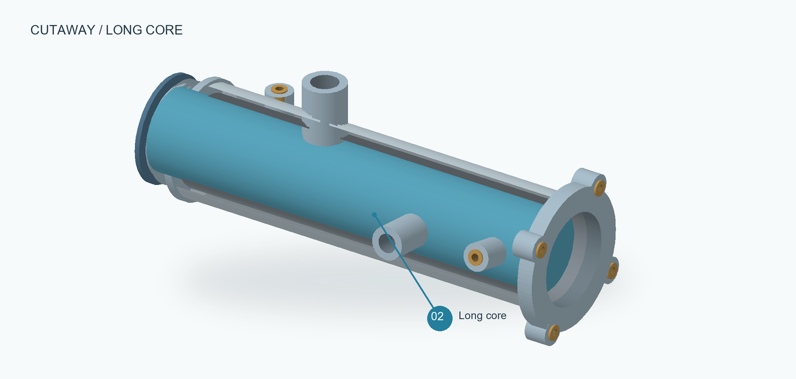
Feature 02 / core position and a proposed internal cooling path.
02 Cooling and demolding
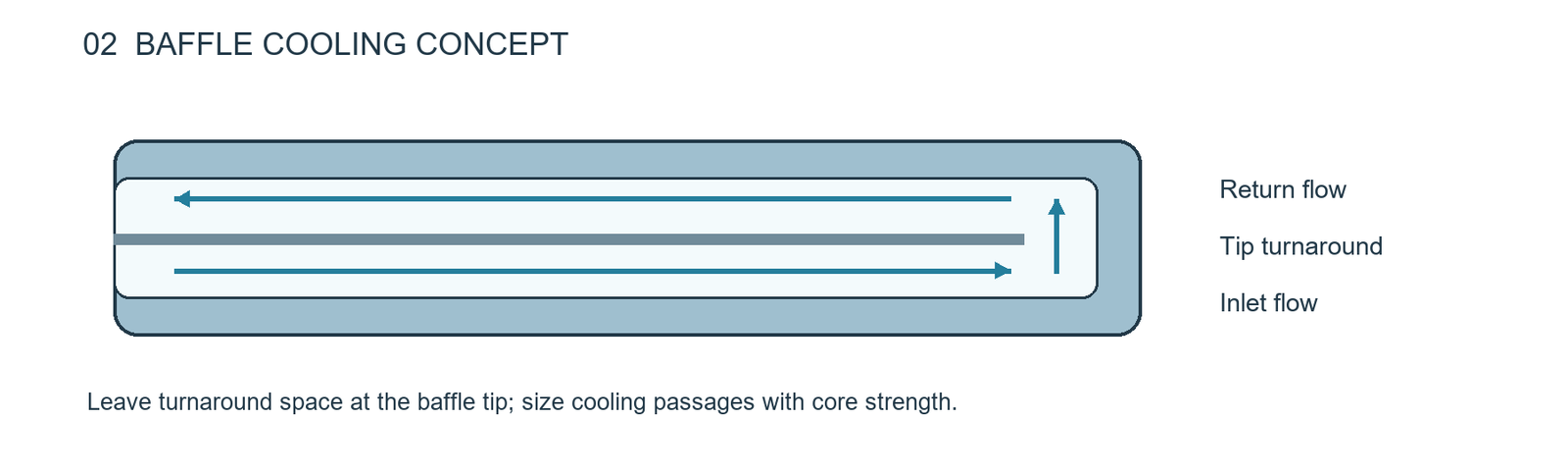
Design core cooling and part release together
The deep bore traps heat, and shrinkage grips the long core. Stronger cavity-side cooling alone does not address the hot inner wall or the long sliding contact during demolding.
Our recommendation
Start with baffle cooling to carry water toward the core tip and back; use a bubbler where space is constrained. Add internal draft within assembly limits and eject through a load-bearing end, avoiding concentrated force on the thin tube wall.
Feature 04 / all seven locations and the recommended process sequence.
04 Insert installation
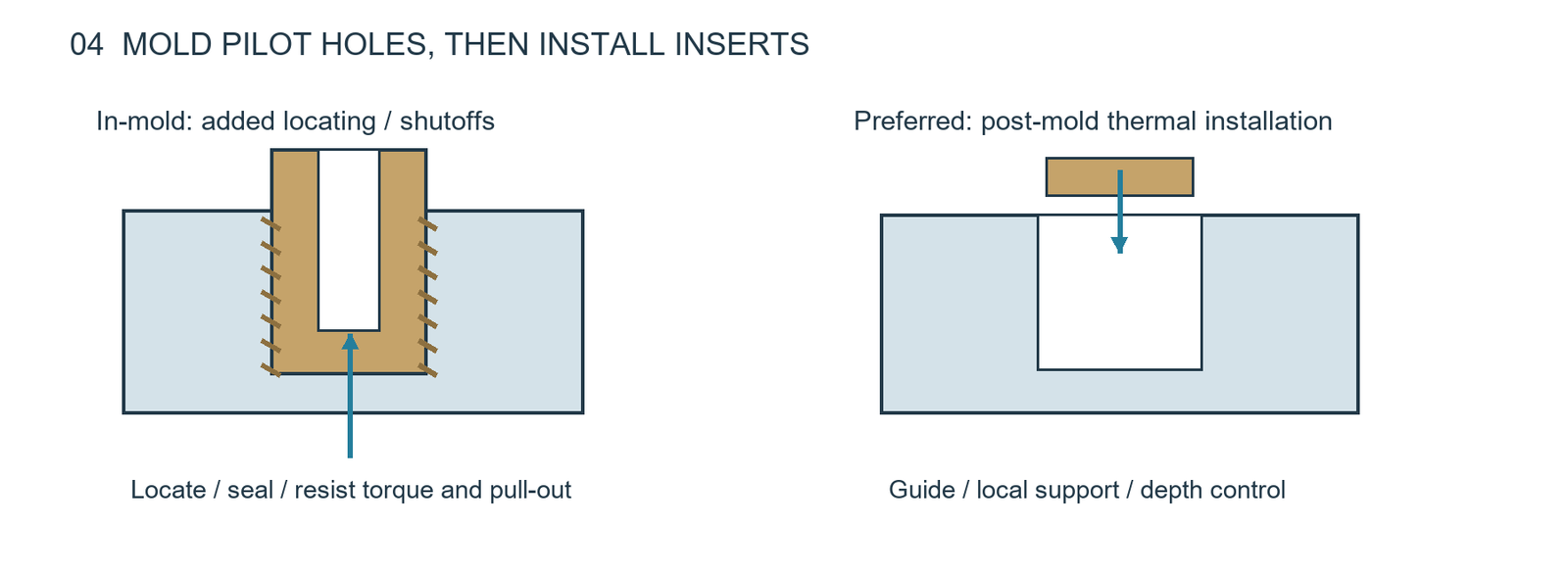
Mold the pilot holes. Install all seven inserts afterward.
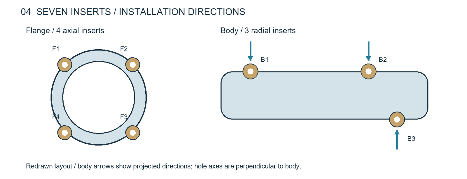
Four axial inserts at the flange and three radial inserts on the body require different loading directions. In-mold insertion adds locating and sealing work in the same space needed by port cores and slides.
Our recommendation
Use post-mold installation. For a thermoplastic housing, we prefer thermal installation with dedicated inserts that resist pull-out and rotation. Support close to each boss root so installation force does not ovalize the tube.
Flange · 4 positionsAn axial guide fixture sets direction and depth.
Body · 3 positionsAn indexing fixture aligns each hole with local support.
A closer look
The details behind the decisions
Expand the topics relevant to your own design.
03Flange transition: reduce the thickness step
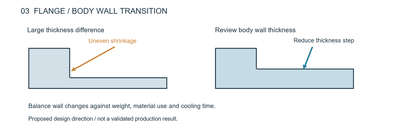
The thick flange cools more slowly than the tube wall. More packing pressure alone cannot remove the shrinkage difference.
We recommend: Review a modest increase in body wall thickness where bore and assembly clearances allow, then blend the transition. Core out non-functional thick areas behind the flange instead of thickening the entire body.
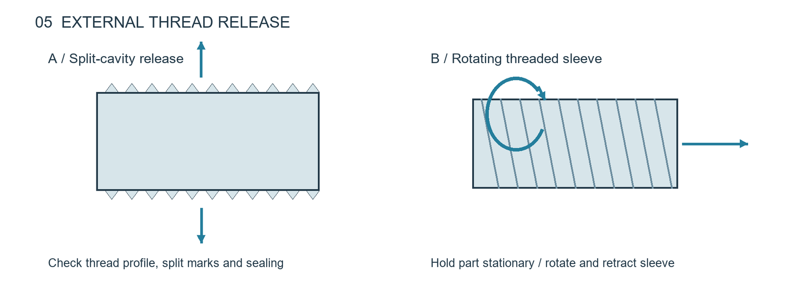
05External thread: start with split-cavity release
Ports and bosses constrain rotation of the complete housing. We therefore release the external thread independently, starting with a split cavity sized for the thread profile and withdrawal travel.
If mating accuracy or appearance rules out split marks, use a rotating threaded sleeve with the housing held stationary. Carry demolding torque through a load-bearing feature.
Add a pilot-hole lead-in and allow space for the insert and displaced plastic. Guide the installation head and control depth and dwell; maintain location during cooling. Add removable internal support through the flange opening if needed.
Direct cold pressing is not our first choice because it can split the bosses. Establish the installation window through thread gauging, height, torque and pull-out checks. Thermal installation assumes a compatible thermoplastic; if the material does not suit heating, keep the post-installation route and change the fixing method.
06Mold details: filling, core support and shutoffs
Filling and venting: Review flow around the port cores, balance the gate layout using filling analysis, and vent at final-fill and flow-meeting locations.
Core support: Use available end features for additional location without obstructing cooling. If a trial shows uneven walls, investigate flow loading and core location first.
Shutoffs: Use serviceable contact features between port cores and the long core; avoid thin, fragile sealing edges.
Functional surfaces: Keep gates, ejector marks and flash-removal work away from flange datums, mating threads and sealing zones.
Case scope: These are engineering recommendations based on the available geometry. No molding-trial or production-validation results are reported. Illustrations preserve manufacturing features while simplifying the design; positions, proportions and thread profiles are not production specifications.
Start with your design
Similar challenges in your plastic part?
Send your geometry and assembly requirements so we can review the molding approach before tooling.